
Everything you need to know about LTE / FTTA Deployment Using Multimode Fibre
Mobile network providers are increasingly deploying Fibre To The Antenna (FTTA) technology solutions in order to minimise the deployment time for their RAN expansions.
FTTA replaces the traditional coax cable that ran to the top of the tower with optical fibre, and repositions components such as the Remote Radio Unit (RRU) to the top of the tower. The fibre connecting the RRU is run to a baseband unit that can either be deployed at the bottom of the tower or can be remotely located, allowing a single BBU to connect to multiple towers in a distributed manner.
Only the short distance between the RRU and the antenna are left using coax cable.
This change in the architecture of the tower means that new tools and methods are required to turnup new tower locations.
Check out the detailed description about the LTE/FTTA deployment and testing
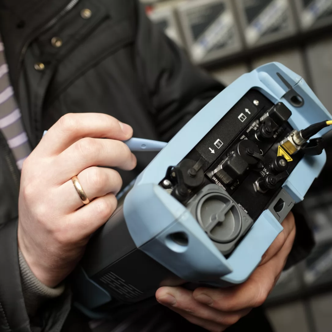
LTE/FTTA Test Location and Method


Connector cleaning

Connector inspection

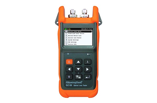
Optical power measurement

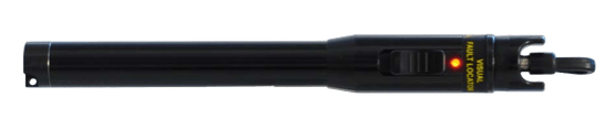
Visual fault location
Reference Setup
- Clean, and then inspect the optical connector on the light source.
- Clean and inspect end A of patch cord #1.
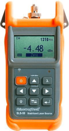
- Connect end A of patch cord #1 to the light source port.
- Clean and inspect end A of patch cord #2.
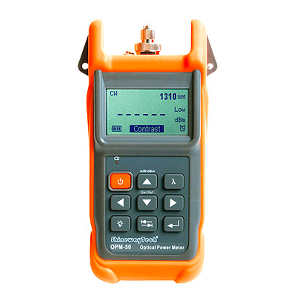
- Connect end A of patch cord #2 to the power meter.
- Clean and inspect end B of patch cord #1 and end B of patch cord #2.
- Connect end B of both patch cords to one side of a duplex LC adapter (if using dual LC connectors).
- Clean and inspect the loopback device.
- Insert the loopback into the duplex LC adapter.
- Select 850 nm on the light source.
- Select 850 nm on the power metre (CW mode; output should be -5 dBm).
- Switch on the light source and turn on the output signal.
- Ensure the reading on the power metre is approximate–7 to -8dB. If the recorded power is lower than expected the connectors should be cleaned and inspected again. If this does not resolve the problem the patch cords/loopback should be replaced.
- Press Ref on the power meter; the reading should be 0.00 dB and should not vary by more than .2 dB as the fibre is moved around.
- Disconnect the loopback and LC adaptor from test leads and protect end faces using caps.
- Move the loopback and LC duplex adaptor to the top of the junction box or RRU unit. Note: Fibre cleaning and inspection will also be required at the remote end before connection of the loopback.
Inspection and Test at Base Junction Box
- Connect the required trunk pair into the duplex LC adapter on the patch- cord microscope.
- Inspect and test connector #1.
- If test fails, clean the connection again and retest.
- Save the test result with the naming convention Trunk# – Fibre# – Pair#.
- Repeat for connector #2 and slide the duplex adapter across.
- Save the test result with the naming convention Trunk# – Fibre# – Pair#.
- Plug the trunk pair into the duplex adapter in the junction box.
- Proceed to loss measurement.
Loss Measurement
- At base junction box, clean and connect end B of test leads to the required trunk pair ports (end A is connected to the light source and the power metre).
- At the top of the tower, clean the end of the jumper cable at the RRU end, clean the loopback, and connect the jumper cable to the loopback with the LC duplex adapter
- Record the loss value on the optical power meter (the value should be <=3 dB) by pressing the Save button. This will link automatically to the last inspection report saved
- Move test fibres to next fibre pair in the base junction box
- Move the loopback on the duplex LC adapter to the next jumper pair. 6. Move to Inspection Step 1.
Your Frame LTE/FTTA Toolkit
Order your LTE/FTTA deplyment toolkit now